
LoRa DIY Long Range Data: REYAX RYLR999 LoRa to Bluetooth Bridge
Published by Vivian van Zyl in ESP32 Microcontrollers the 03/28/2026 at 06:08 pm

Ever wished you could move a small amount of data over miles without relying on Wi-Fi, cellular service, or a full mesh network? That was exactly the point of this build: use LoRa as the long-range link, then use Bluetooth as the “local display” so you can read messages directly on your phone.
This setup uses REYAX RYLR999 chips, which combine LoRa 915MHz and Bluetooth in one module. The cool part is the bridging approach: send over LoRa from one node, and on the receiving side bridge the data back out to Bluetooth so your mobile app can subscribe to what arrives.
What makes the RYLR999 interesting?
Inside each node is the latest REYAX silicon (the RYLR999). What makes these chips especially compelling for DIY is that they bring both radios to the table:
- LoRa (915MHz) for long-range transmission
- Bluetooth for reading data locally
There are also some practical details that make builds easier. The nodes can provide a strong transmit capability (described as 30 dBm LoRa output) and they support proper external antennas. Earlier versions often relied on smaller built-in antenna setups. Here, you get IPX connectors, so you can mount real antennas tuned for:
- 915MHz LoRa
- 2.4GHz Bluetooth
Finally, there are separate UART interfaces for the LoRa side and the Bluetooth side. The bridge is conceptually simple: feed data into the module over one interface, transmit across LoRa, and then output it over the other side so a phone can see it.
The core idea: bridge LoRa to Bluetooth
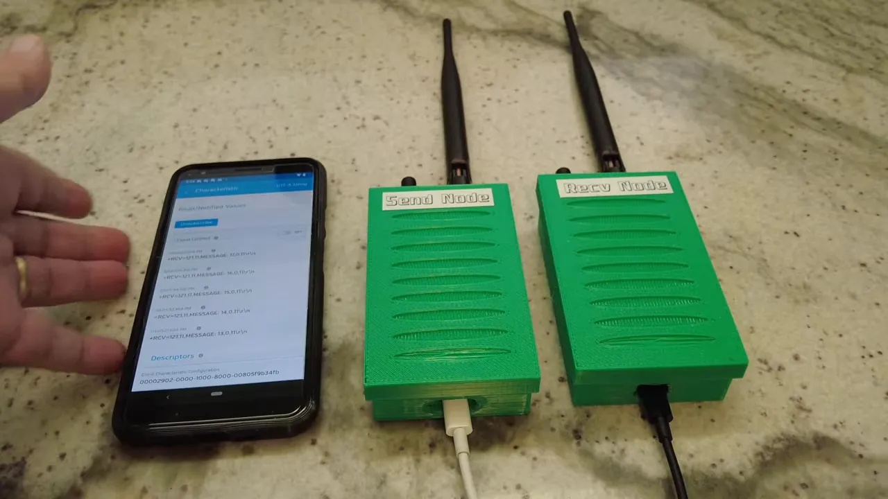
The project’s architecture is two nodes:
- Sending node: generates or receives a message, sends it over LoRa.
- Receiving node: receives the LoRa payload, bridges it out over Bluetooth.
On the phone side, the user workflow is straightforward. A mobile app connects via Bluetooth LE, subscribes to the incoming characteristic, and prints the received messages as they arrive.
Why this matters (beyond “range”)
This isn’t about building a full LoRa network or replacing every connectivity option. It’s a lower-level approach: if you only need to move small packets of data from point A to point B, LoRa does the long-distance part, and Bluetooth does the human-friendly part.
That’s why the idea fits real-world sensor use cases like:
- water level monitoring
- agriculture and livestock telemetry
- emergency and off-grid alerts
- infrastructure monitoring
- DIY prototypes that need “it just works” connectivity
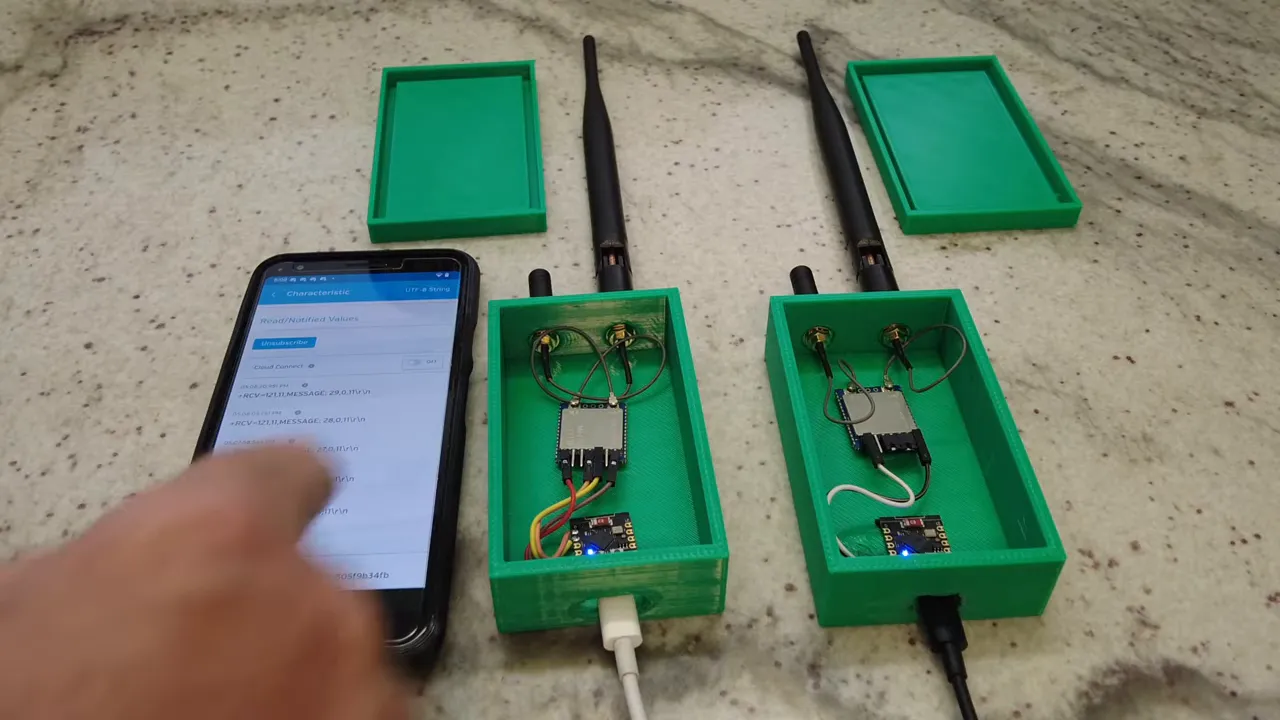
Building the nodes (3D printed cases + real antennas)
Having chips sitting on a bench is annoying long-term, so the build started with 3D-printed enclosures. Each enclosure includes:
- two holes on top to mount the LoRa and Bluetooth antennas
- a bottom opening so the node can be powered
After the mechanical build, the first steps were functional testing:
- connect the chip to a PC using a USB-to-serial adapter
- send commands like reset and addressing (AT-style commands)
- confirm that a “hello” message successfully transmits and is received
Then the Bluetooth bridging behavior was added via the Bluetooth side jumpers/wiring so that messages appear on the phone app.
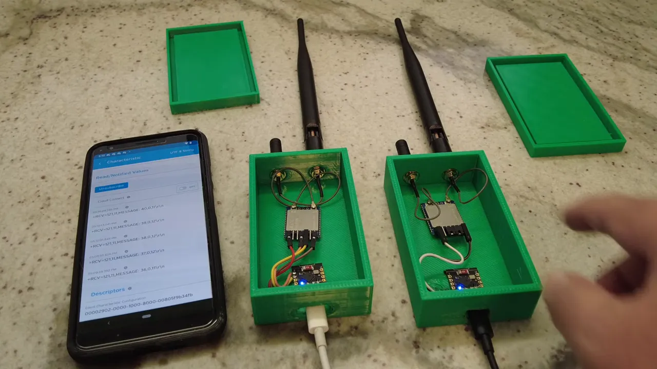
Generating test messages with ESP32-C3
To prove the concept reliably, an ESP32-C3 was used as a message generator on the sending node side. The reason is simple: it’s easy to send a periodic payload without needing external sensors while you validate the radio link.
The sending logic was “send every 10 seconds.” Each packet contained a small string like:
- “message: 52”, then 53, 54, and so on
Those messages travel:
- from the ESP32-C3 to the REYAX module via UART
- over LoRa to the receiving REYAX node
- then bridged out over Bluetooth LE
- and finally displayed in the mobile app
For the phone UI, the app used was LightBlue. The workflow was:
- connect to the device via Bluetooth LE
- select the correct characteristic
- subscribe to “messages received”
- display incoming payloads as UTF-8 strings
Power notes you should not skip
The demo used power banks for convenience, but the important lesson is voltage compatibility:
- These chips do not work on 3.3V.
- They require 5V.
So even if your ESP32-C3 runs happily at 3.3V, the LoRa/Bluetooth nodes still need the proper 5V supply. In this build, the ESP32-C3 primarily served as a logic sender, while the Bluetooth-focused side used wiring to ensure it still received 5V.
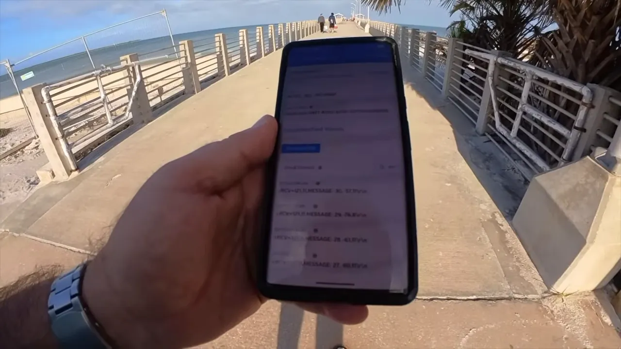
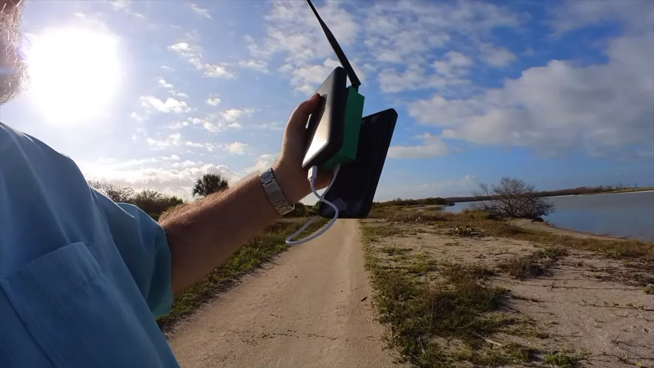
Real-world range test at Fort De Soto
The most convincing part was taking the system outside and seeing what it could do with actual obstructions, distance, and real antenna placement.
Pier to far parking lot
On the pier, the receiver kept getting packets as the sending node transmitted every 10 seconds. The narrator notes packet numbers climbing steadily, and then continued movement toward longer distances.
As the receiver moved farther, the link still produced usable traffic, even showing error packets along the way. Importantly, the test clarified that the result was achieved with a standard antenna, not an exotic custom antenna setup.
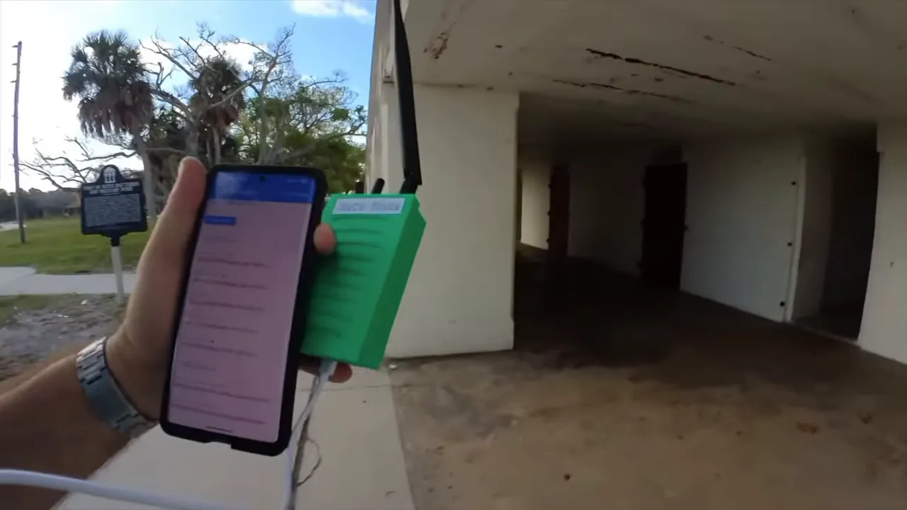
North beach distance (including “behind trees and bushes”)
The system was carried toward the far side and into locations where signal might be partially blocked. The receiver showed reliable packet reception during movement and reported values that included:
- RSSI (signal strength)
- SNR (signal to noise ratio)
Even when RSSI dropped significantly, the receiver still managed at least some successful decodes. That’s exactly what you want to know for sensor deployments: you need to know where “maybe it will work” turns into “it’s consistently readable.”
Concrete bunkers: still receiving, but decoding may fail
One of the more brutal tests was inside bunkers. The receiver recorded activity (it could “receive something”), but decoding failed with an error reported (an “Error 12”), which is a realistic reminder:
- RF can sometimes penetrate, but decoding depends on enough SNR.
- Expect better results outdoors than inside thick concrete.
Closing the loop: finding the source
The receiver eventually got much stronger RSSI again closer to the sending node, and packet numbers increased reliably. As the nodes approached alignment and separation decreased, the link became clearly stable.
That last part is practically useful. In the field, knowing whether you can “hunt down” a transmitting sensor by walking toward increasing signal helps with commissioning and troubleshooting.
Common DIY applications for this LoRa + Bluetooth bridge
This bridging approach is a great fit when you want:
- low data rates (small status updates)
- long distance without Wi-Fi or cellular
- easy inspection using a phone app
- a simple receiver that outputs readable Bluetooth data
Examples that map well to the demo:
- a pump or tank sensor sending periodic “level” values
- a gate sensor that reports “open/closed”
- a weather station that transmits short summaries
- off-grid alarms that trigger periodic updates for confirmation
FAQ
Is this the same thing as Meshtastic or LoRaWAN?
No. This is a simpler “link” approach. It doesn’t rely on a mesh system or LoRaWAN infrastructure. The goal is point-to-point long-range transmission with a Bluetooth bridge for the user interface.
Why bridge to Bluetooth at the receiver?
Bluetooth makes the received data easy to view on a phone without extra gateways. Your mobile app can connect via Bluetooth LE and subscribe to the incoming messages directly.
What antenna setup is required?
The build uses external antennas mounted through IPX connectors. A 915MHz LoRa antenna handles the long-range link, and a 2.4GHz Bluetooth antenna improves the local reception. The range test specifically mentions using a standard antenna, which still performed well outdoors.
Can I power these nodes with 3.3V?
No. The chips require 5V operation. Even if your microcontroller runs at 3.3V, provide 5V to the RYLR999 nodes.
How often should you send data?
For a test, the demo used a message every 10 seconds. In real deployments, you can tune update rate based on battery life and how quickly you need the data.
Where can the project files and source code be found?
Project files are available at the project link listed below, and the “Bluetooth to LoRa Bridge” project includes the hardware and software components used in this approach.
Project link
Project files: Bluetooth to LoRa Bridge
Links: (Note: As an affiliate, I earn from qualifying purchases)
- RYLR999 Amazon
- RYLR999 Digkey
- RYLR999 eBay
- RYLR999 US Distributor Lemos International
- RYLR999 US Distributor Micro Technology Group
- 3D Printer I use (1 color)
- 3D Printer I use (multi color)
- USB To Serial
- Project files