
Build Guide: RAK 1W Meshtastic Node with Solar Power
Published by Vivian van Zyl in Meshtastic the 01/31/2026 at 12:57 am

I built a RAK 1W Meshtastic node that runs from a 5W solar panel and a pair of 18650 cells (around 7,000 mAh combined). This guide walks through the real-world decisions, wiring, and small modifications I made to get reliable one-watt performance outdoors. If you want a compact, solar-powered LoRa node capable of higher transmit power, the RAK 1W setup described here is a practical path.
Table of Contents
- Why choose a RAK 1W node?
- Parts, tools, and quick shopping list
- Power considerations (don’t rely on USB alone)
- Step-by-step build
- Quick checklist before closing the box
- Testing and field deployment
- What I learned (short version)
- FAQ
- Final notes
Why choose a RAK 1W node?
The RAK 1W option boosts transmit power compared with standard LoRa modules. That means longer range and a more robust link for Meshtastic or custom LoRa networks. But higher RF power brings higher electrical demands and more heat, so the build balances power delivery, cooling, and waterproofing.
Parts, tools, and quick shopping list
The essentials I used for this RAK 1W build:
- RAK 1W (RAK13302 style) rack board configured for 915 MHz
- Waterproof enclosure (thick-walled ABS or polycarbonate)
- 5W adjustable solar panel and solar charger with 5V output
- Two 18650 batteries (3,500 mAh each ≈ 7,000 mAh total)
- Type N (or compatible IPX) antenna connector and a 915 MHz antenna
- 30 mm 5V fan plus a KSD temperature switch for automatic control
- 3M double-sided tape, silicone sealant, cable ties, basic soldering tools
Power considerations (don’t rely on USB alone)
The key thing I learned was that the RAK 1W board can draw more current when transmitting at full power. Running it directly from a USB 3.3V rail can prevent the radio from reaching full output. Use a battery or a dedicated 5V external supply from a solar charge controller. Also set the board jumper to external if you are powering it from a separate 5V source rather than its internal battery connector.
Step-by-step build
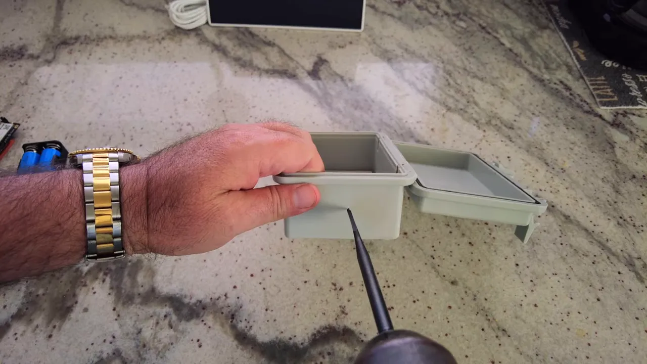
1. Case preparation and antenna hole
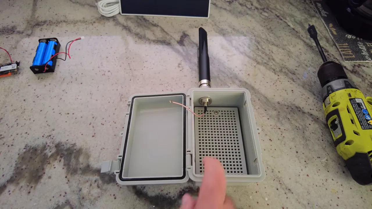
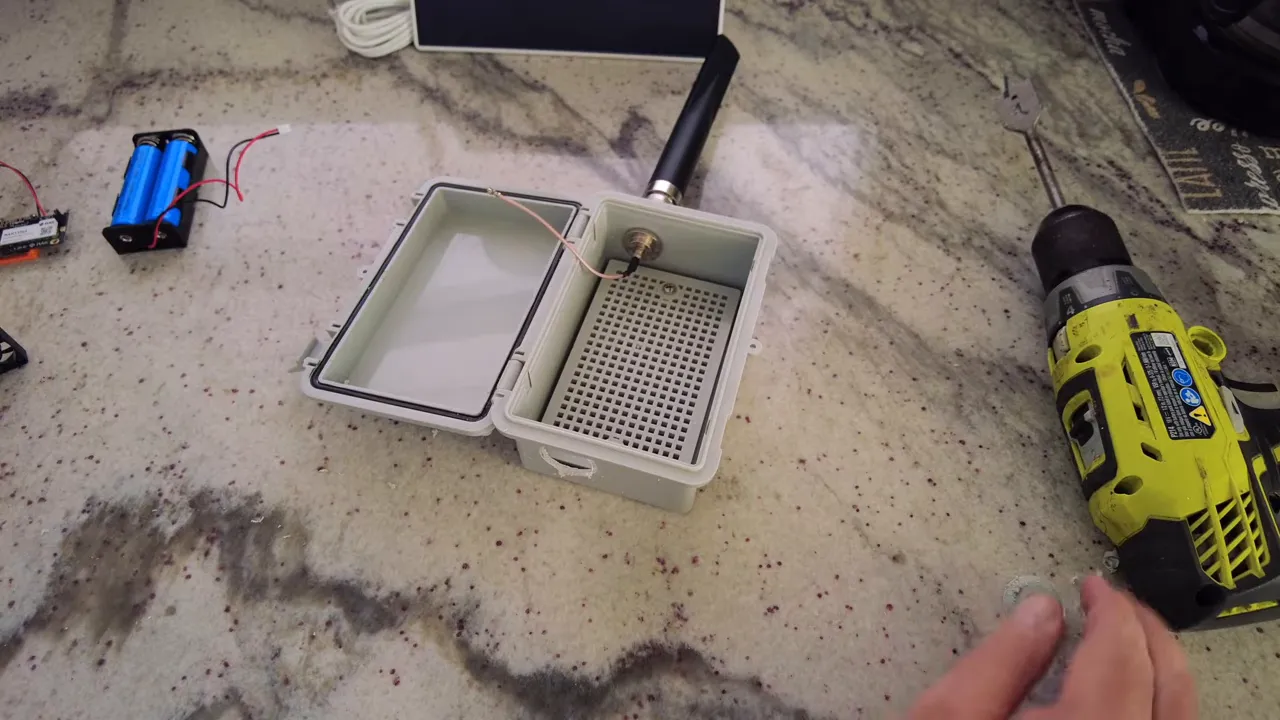
Mark the top of your enclosure for the antenna. I drilled a 5/8" hole for the connector and used the rubber gasket and nut provided to seal the feedthrough.
Tighten the nut so the gasket compresses against the case. If you plan to mount the antenna off-center to make room for batteries and the solar charger, plan that before drilling.
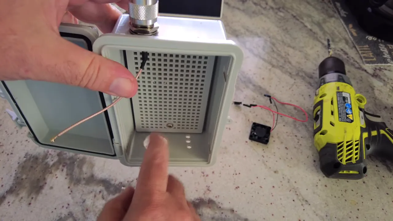
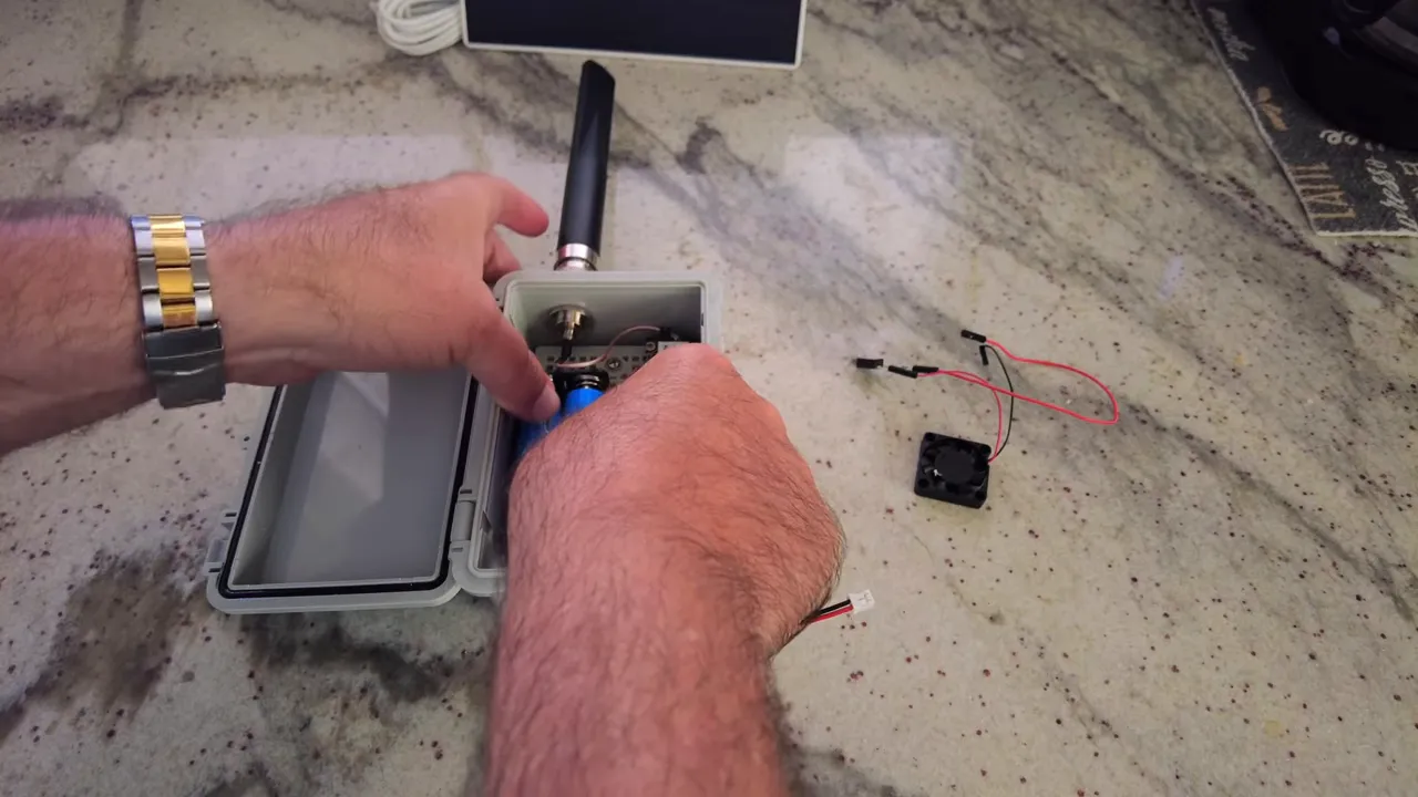
2. Cooling: fan and temperature switch
With 1W RF output and Florida sun conditions, heat can add up. I added a 30 mm 5V fan mounted to the bottom of the enclosure and a KSD-style temperature switch (normally open). The switch closes around 105–107°C to start the fan, and opens again once it cools (roughly in the 70–80°C range), so the fan only runs when needed.
I also drilled a few intake holes on the side so the fan can pull fresh air in and push warm air out. Small intake holes keep rain out while allowing airflow.
3. Mounting batteries and the solar charge controller
The solar charger I used accepts two 18650 cells and provides a stable 5V output. I mounted the battery holder and the charge controller inside the lid with 3M double-sided tape and small 3D-printed brackets. Keep the batteries away from the antenna as a general practice.
The charger typically exposes a few outputs (5V, 3.3V, ground). Use the 5V rail to feed the RAK board when you want full transmit capability. If you use the board’s internal battery input instead, set the jumper accordingly.
4. Wiring the solar panel and sealing feedthroughs
Route the solar panel cable through a drilled hole, strip the wires, and secure them into the charger’s PV input (observe polarity). Test that the charger indicates incoming solar voltage before finalizing.
Mount the external solar panel bracket with short screws and seal all holes and screw heads with silicone to keep the enclosure watertight. Add a dab of silicone around the antenna feed and solar cable entry as well.
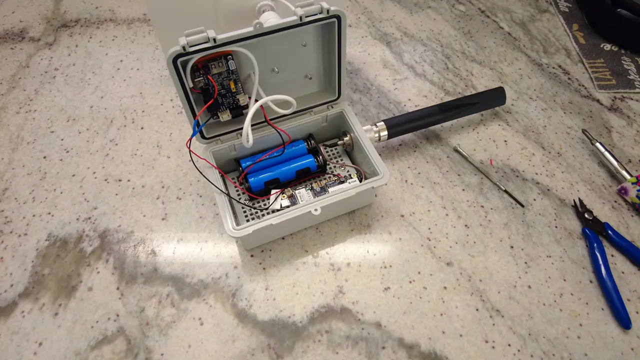
5. Antennas and connectors
The recommended connector may be a specific standard, but many compatible IPX or Type N adapters match the same mechanical dimensions. I installed a Type N bulkhead at the top and attached a 915 MHz antenna. Keep the Bluetooth/BLE antenna separated from the main LoRa antenna and mount it on the side to reduce interference.
6. Flashing Meshtastic firmware and pairing
To flash Meshtastic, put the RAK board into DFU mode, connect over USB, and copy the UF2 firmware file to the mounted drive. I keep a backup of the original UF2 before overwriting the firmware.
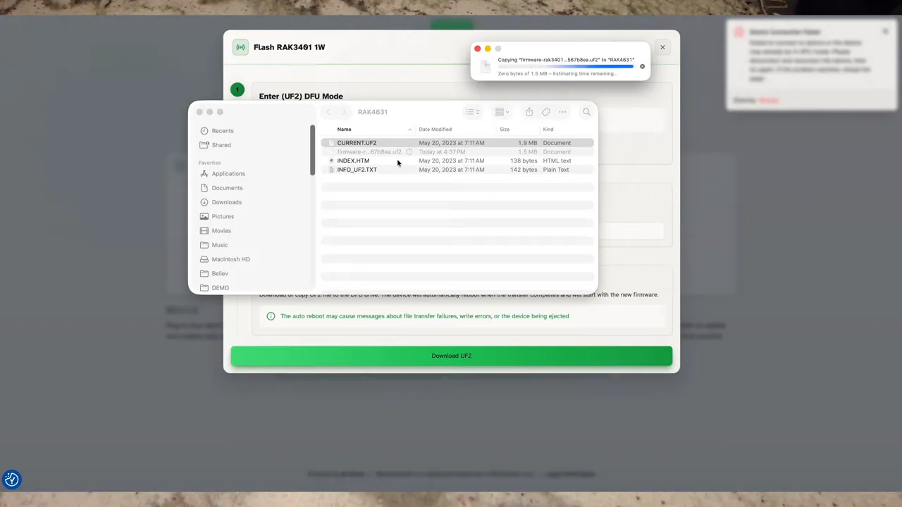
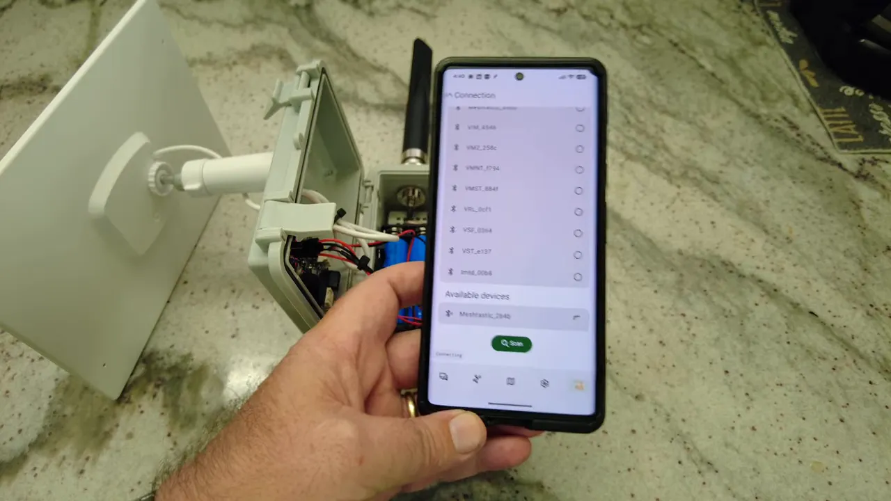
After flashing, use the Meshtastic mobile app to pair via Bluetooth. Set your region (United States for 915 MHz) and verify the transmit power setting. The RAK 1W board supports higher transmit power levels—set it to the appropriate value for your hardware and regional regulations.
Quick checklist before closing the box
- Jumper set to external if powering from 5V solar charger
- Solar panel wiring secured and polarity checked
- Temperature switch positioned near the batteries or warmest spot
- BLE antenna mounted away from LoRa antenna
- All cable entries and screw heads sealed with silicone
- Fan wired to 3.3V or 5V as chosen, with temperature switch inline
Testing and field deployment
Power the unit from the battery and verify the board boots. Check Meshtastic pairing over Bluetooth and confirm the node registers online. Watch the node during a transmit cycle to ensure the supply holds up and the fan engages only when necessary.
Mount the enclosure in a sunny location with the solar panel angled to maximize daily charge. Monitor battery voltage and daily charge cycles for the first few weeks to confirm the 5W panel and 7,000 mAh battery configuration meet your uptime goals.
What I learned (short version)
- The RAK 1W board wants a capable 5V source to reach full transmit power.
- Thermal management is inexpensive and effective: a small fan with a temp switch worked well.
- Simple sealing with silicone around feedthroughs protects the electronics.
- Flashing Meshtastic via UF2 is straightforward—keep a backup of the original UF2.
FAQ
Can I run the RAK 1W board from a USB port?
You can run the board from USB if the supply provides stable 5V and sufficient current. In practice, an external 5V solar charger or battery is more reliable when attempting full 1W transmit power.
Where should I set the jumper for external power?
Set the jumper to external when you are supplying regulated 5V from a charger or external source. Use internal if you are relying on the board's own battery input.
Is the temperature-controlled fan necessary?
Not strictly necessary, but recommended in hot climates or when the enclosure may see prolonged sunlight. The KSD switch lets the fan run only when needed, conserving power.
How do I flash Meshtastic firmware?
Put the board into DFU mode, connect via USB, and copy the UF2 firmware file to the mounted drive. Keep a backup of the existing UF2 before overwriting.
Final notes
Building a reliable solar-powered RAK 1W Meshtastic node is mostly about making the power delivery and thermal management choices that match your environment. The combination of a 5W solar panel, a 7,000 mAh battery pack, and a simple temperature-controlled fan gave me confidence to mount the node outdoors and test range and uptime in the coming days.
If you build one, focus first on power wiring, jumper selection, and a good seal around cable entry points. The rest—antenna placement, fan, and app configuration—are adjustments that you can refine once the node is live.
Links:
- Waterproof Case - https://amzn.to/4r4xuhf
- 5W Solar Panel - https://amzn.to/4a0rxu2
- KSD 01-F Temperature Switch - https://amzn.to/3NLeEgb
- Solar Charger with 5V - https://amzn.to/4t3RRfL
- 18650 Battery - https://amzn.to/3HJvbOz
- 5V 30mm Fan - https://amzn.to/4lgqP03
- Type N Connector - https://amzn.to/463koca
- 915Mhz Alfa Antenna - https://amzn.to/3TsSOxt
- RAK 1W (They are struggling with stock) - https://store.rokland.com/
- 90 Degree Angle USB C Flush Panel Mount - https://amzn.to/4tdFv4T