
How to Connect Sensors to Meshtastic: I2C and UART Guide
Published by Vivian van Zyl in Meshtastic the 09/22/2026 at 10:01 pm

Adding a GPS, temperature sensor, or small external display is a great way to make a Meshtastic node much more useful. A standard Heltec V4 running Meshtastic can report environmental data across the LoRa mesh, show it on a local OLED display, and support a GPS module for position information.
The two main ways to connect these peripherals are UART and I2C. They are both straightforward once you understand which jobs they suit, how the pins are wired, and where Meshtastic expects the configuration.
What You'll Learn
- UART connects a GPS through crossed TX and RX lines on dedicated GPIO pins.
- I2C lets sensors and OLED displays share SDA and SCL through individual device addresses.
- Heltec V4 telemetry can detect supported I2C environmental sensors with minimal configuration.
- Environmental readings can appear locally on OLED and remotely across the Meshtastic mesh.
Table of Contents
- Hardware Used for This Meshtastic Sensor Setup
- Find the Right Pins on a Heltec V4
- UART vs I2C: Which Connection Should You Use?
- Wiring an I2C Sensor and OLED Display
- Configure a UART GPS in Meshtastic
- Enable I2C Telemetry for an Environmental Sensor
- Test the Temperature Sensor
- Show Environmental Data on the External OLED
- Read Sensor Telemetry From Another Meshtastic Node
- Build a More Useful Meshtastic Node
Hardware Used for This Meshtastic Sensor Setup
This setup uses a screenless Heltec V4 node with its LoRa antenna and WiFi/Bluetooth antenna attached. The original onboard display has been removed, which makes it a useful example of how an external screen can be added wherever it makes sense for a custom enclosure.
The peripherals are:
- A GPS module intended for a UART connection
- An environmental sensor, such as a BME280 or BME680, connected over I2C
- A small I2C OLED display
- An I2C breakout board to extend the bus from one device to another
Meshtastic already supports a range of I2C peripherals, including environmental sensors, voltage monitors, and barometric-pressure sensors. The supported sensor list and I2C addresses are useful references when planning a build, especially if several devices will share the same bus.
Find the Right Pins on a Heltec V4
Start with power. For the peripherals in this build, use the node's 3.3V pin and ground. Avoid assuming that a 5V connection is appropriate. These small sensors and displays are typically intended to run at 3.3V with the Heltec.
On this Heltec V4 setup, the selected UART pins are:
- GPIO 47
- GPIO 48
The I2C pins on this board are:
- GPIO 17
- GPIO 18
Pin assignments differ between boards, so always confirm the pinout for the exact hardware in use. The Heltec V4 pinout is the important reference here, not a generic pin map from another Meshtastic device.
UART vs I2C: Which Connection Should You Use?
UART is ideal for GPS modules
UART is a direct serial connection between the Meshtastic node and one peripheral. It uses two data lines:
- TX, transmit data
- RX, receive data
The connection is crossed: the node's TX goes to the GPS module's RX, and the node's RX goes to the GPS module's TX. Both sides must communicate at a compatible baud rate, with 9600 baud being a common GPS starting point.
UART is a good fit for a GPS because it is a point-to-point connection. One UART line normally talks to one module.
I2C is ideal for sensors and displays
I2C uses two shared signal wires:
- SDA, serial data
- SCL, serial clock
Unlike UART, I2C works as a bus. Several devices can share the same SDA and SCL wires, provided each device has its own I2C address. That makes it ideal for combining an environmental sensor with an OLED display on the same node.
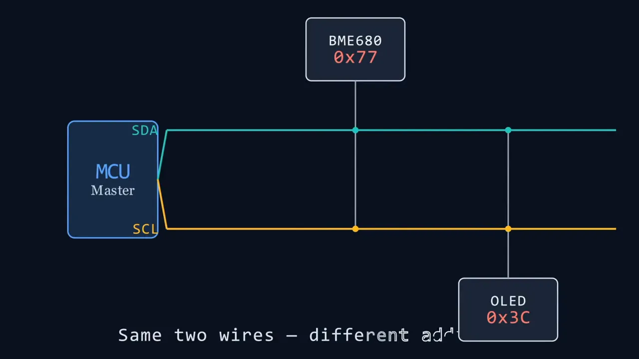
In this example, the BME680 sensor and OLED display are both connected to the same I2C bus. The sensor reports environmental information while the display provides local status and telemetry readouts.
Wiring an I2C Sensor and OLED Display
The I2C wiring is simple. Every device needs power and ground, followed by the two shared data connections.
- Connect the Heltec's ground pin to the ground connection on the I2C breakout.
- Connect the Heltec's 3.3V pin to the breakout's positive power connection.
- Connect the Heltec I2C SDA pin to SDA on the breakout.
- Connect the Heltec I2C SCL pin to SCL on the breakout.
- Connect the environmental sensor to one side of the I2C breakout.
- Connect the OLED display to the other side to continue the I2C bus.
The breakout board makes the shared-bus concept easy to see. The bus arrives from the Heltec, connects to the sensor, and continues to the display. The sensor and screen both receive power, ground, SDA, and SCL, while each responds to its own address.
Once USB power is connected, the breakout board powers up and the external OLED should come alive. Most small OLED modules clearly label their four pins, usually ground, VCC, SDA, and SCL, so there is not much mystery in the wiring.
If you need the parts used here, the relevant hardware links are available for the Heltec V4, BME680 sensor, and OLED display.
Configure a UART GPS in Meshtastic
Meshtastic can connect to the node over Bluetooth, network, or USB. After connecting, open the node settings to configure the GPS.
For a UART GPS, go to:
Device Configuration > Position
Enable position functionality as needed, then scroll down to the GPS pin settings. Enter the two GPIO pins used for the UART connection. In this Heltec V4 example, those are GPIO 47 and GPIO 48.
Meshtastic handles much of the GPS communication automatically. After the pins are assigned, it can try appropriate serial rates and communicate with the module. The key part is getting the physical TX and RX wiring correct and assigning the corresponding pins in the app.
Enable I2C Telemetry for an Environmental Sensor
The I2C side needs very little configuration because the Heltec V4 has known I2C pins. Once the sensor is wired to the bus, enable telemetry in Meshtastic.
Go to:
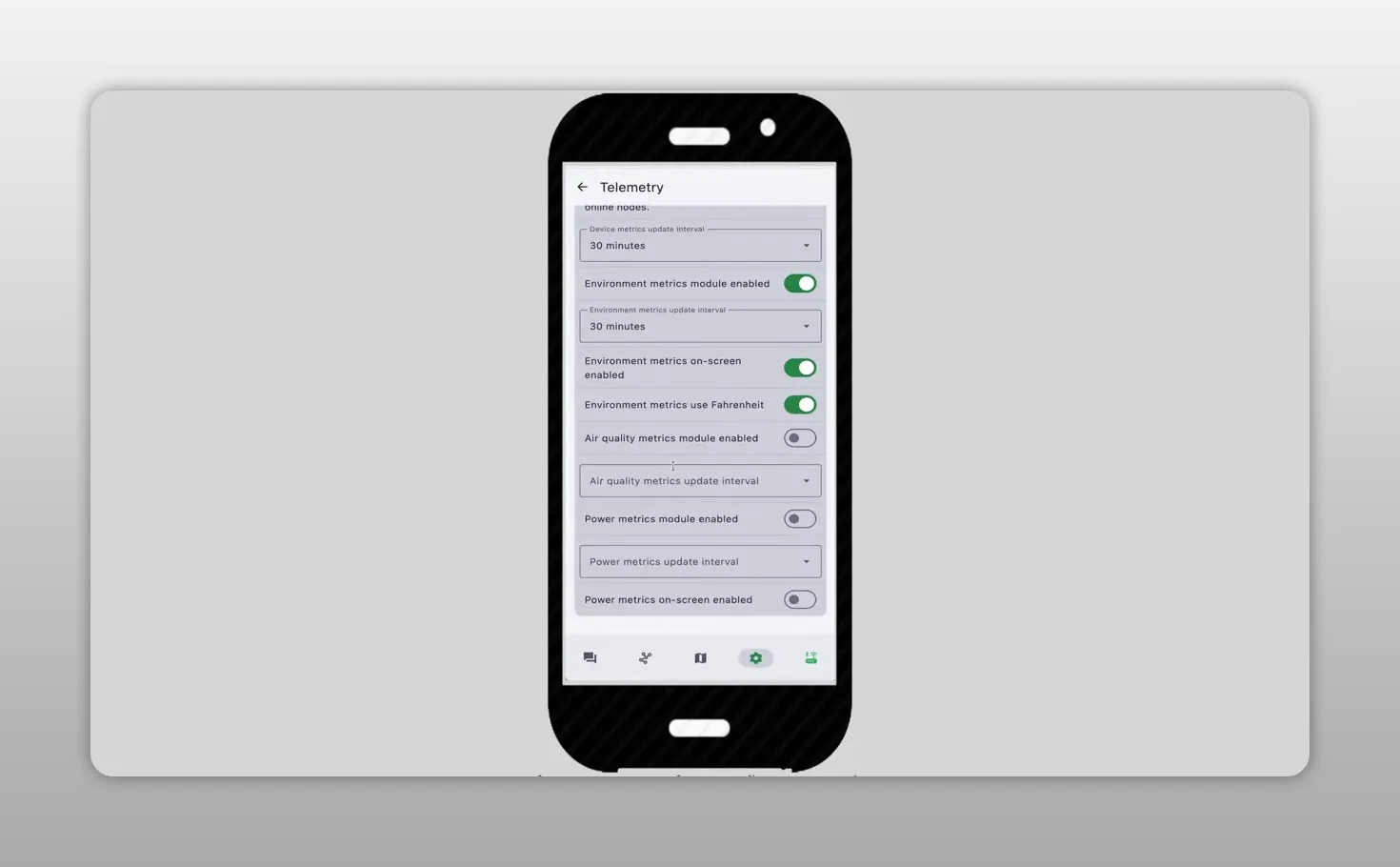
Module Configuration > Telemetry
From there:
- Enable the telemetry module.
- Set the telemetry update interval.
- Choose whether readings should appear in Fahrenheit or Celsius.
- Enable on-screen environmental information if an external display is connected.
In this setup, the node rereads the sensor and sends telemetry across the LoRa network every 30 minutes. The interval should match the purpose of the node. For a general environmental node, a longer interval helps keep traffic down. For testing, a shorter interval makes it easier to confirm that the sensor is responding.
Test the Temperature Sensor
Once telemetry is enabled, the Meshtastic app should begin showing an environmental reading from the node. In this example, the temperature sensor was detected and reporting without any complicated sensor-specific setup.
A quick practical test is to hold the sensor in your hand for a few seconds. The reported temperature should begin to rise. When connected over Bluetooth, the app updates more frequently, around once a minute in this setup, making it easy to see the value change during testing.
If the reading does not appear, check these basics first:
- Confirm that the sensor has 3.3V power and a shared ground.
- Check that SDA and SCL have not been swapped.
- Verify that the sensor is supported by Meshtastic telemetry.
- Confirm that telemetry is enabled in Module Configuration.
- Check the I2C address if more than one device is connected.
Show Environmental Data on the External OLED
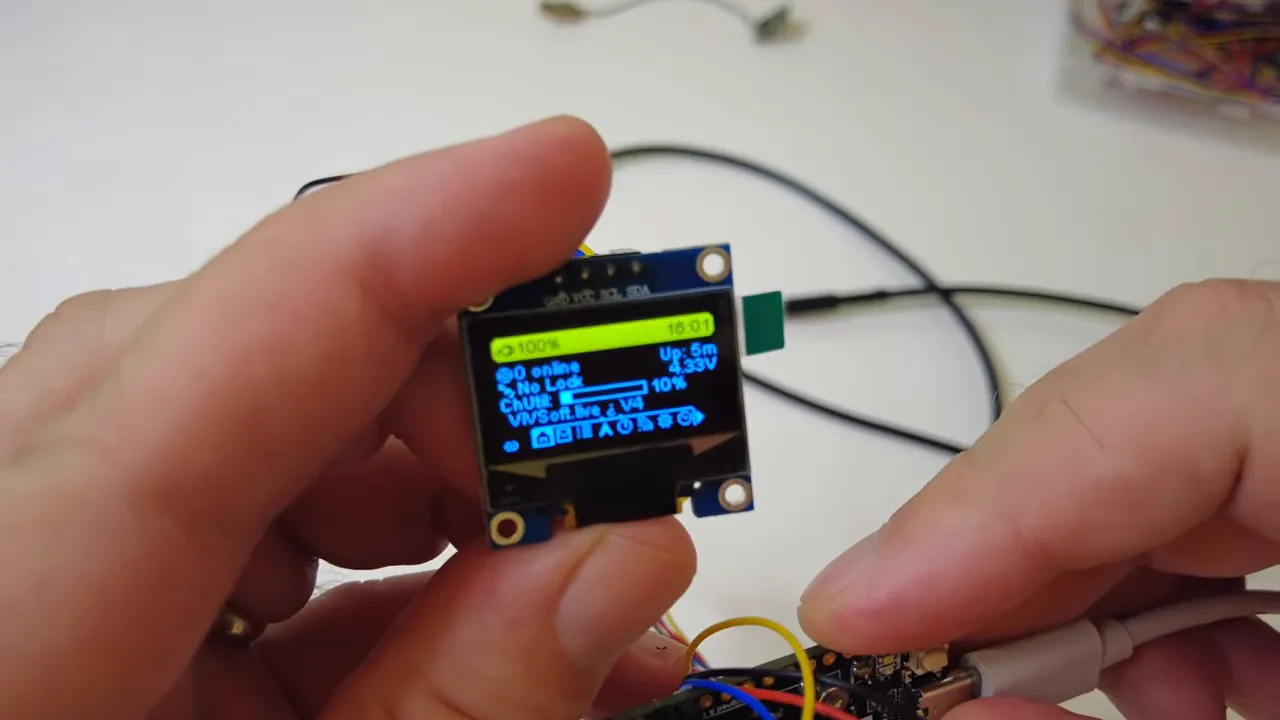
With on-screen environmental metrics enabled, the external OLED can show the same data that appears in the Meshtastic app. Use the node's user button, not the reset button, to cycle through display screens until the environmental information page appears.
The environmental display shows the node identifier and the latest reported reading. This is particularly useful for a custom build where the screen is mounted somewhere visible, even if the main board itself is tucked into an enclosure.
Read Sensor Telemetry From Another Meshtastic Node
The real benefit is that the data is not limited to the local node. Once telemetry is active, the temperature reading is included in the node's information and can be received by other nodes across the LoRa mesh.
Another Meshtastic node on the network can see the reporting node and open its telemetry details to read the environmental information. That turns a simple sensor into a mesh-connected remote monitor.
You can have a normal Meshtastic node with a small sensor and screen attached, place it where it is useful, and still read its data from elsewhere on the mesh. It works like any other node, just with much more useful local information attached.
Build a More Useful Meshtastic Node
A single I2C temperature sensor and OLED display are only the beginning. Since I2C is a shared bus, more supported devices can be added as long as their addresses do not conflict. A GPS on UART can also be added alongside the I2C devices.
The main idea is simple:
- Use UART for a direct device such as a GPS.
- Use I2C for expandable sensors, monitors, and displays.
- Use Meshtastic telemetry to report environmental information over the LoRa mesh.
- Use an external OLED when local status information is useful.
There is very little configuration once the wiring is correct. Meshtastic already has much of the functionality built in, so connecting the hardware and enabling the right module is enough to create a capable environmental telemetry node.
Frequently Asked Questions
Which pins are used for I2C on the Heltec V4?
In this setup, GPIO 17 and GPIO 18 are used for the Heltec V4 I2C connection. Always verify the pinout for the exact board version being used.
Which pins are used for a UART GPS on this Heltec V4 setup?
This example uses GPIO 47 and GPIO 48 for UART. Assign those same pins in Meshtastic under Device Configuration and Position.
Can an I2C sensor and OLED display use the same pins?
Yes. I2C is a shared bus, so the sensor and OLED can share SDA and SCL as long as they have different I2C addresses.
Where do I enable a Meshtastic temperature sensor?
Open Module Configuration, select Telemetry, enable telemetry, set the reporting interval, and enable environmental metrics for the connected supported sensor.