
Meshtastic Solar: Building a Solar-Powered LoRa Node with the SolarXiao Plus Advanced
Published by Vivian van Zyl in Meshtastic the 02/12/2026 at 06:44 pm

Meshtastic Solar setups bring resilient, low-power LoRa networking to remote locations. This guide walks through assembling a compact solar-powered Meshtastic node using the SolarXaio Infrastructure Node Plus Advanced (the SolarXaio Plus Advanced) board. Expect practical tips on polarity, jumper selection, antenna mounting, solar wiring, firmware configuration, and sealing the enclosure so your node can run reliably in the field.
Table of Contents
- Why this board for Meshtastic Solar projects
- Parts and tools (what I used)
- Step-by-step build
- Troubleshooting tips
- What to expect in real deployments
- FAQ
- Final notes
Why this board for Meshtastic Solar projects
The SolarXaio Plus Advanced pairs an nRF52840 processor with a one-watt LoRa radio (E22P 915M30S). That combination gives you Bluetooth provisioning, ample processing headroom, and strong RF range thanks to a 1 W radio with LNA and amplifier. The board also includes a dedicated solar charging circuit, low-voltage protection (around 2.9 V cutoff), and selectable solar input voltage modes. For anyone building a Meshtastic Solar node, that feature set makes it an excellent foundation.
Parts and tools (what I used)
- SolarXaio Infrastructure Node Plus Advanced (nRF52840 + E22P 915M30S)
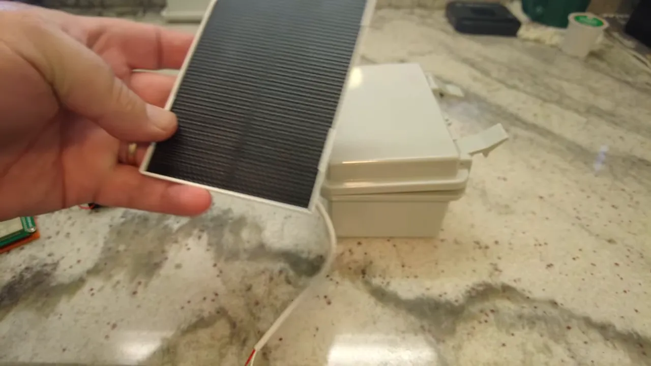
- 3 W 915 MHz solar panel with adjustable mount
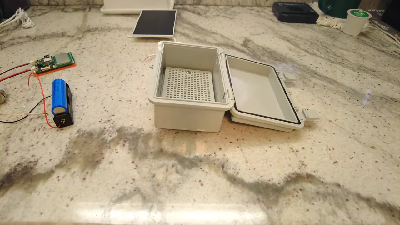
- 18650 3500 mAh battery and battery holder
- Type N connector plus Type N to SMA adapter and SMA antenna
- Waterproof project case and small printed mounting plate
- 3M double-sided tape, heat shrink, silicone sealant, cable ties
- Basic tools: soldering iron, multimeter, drill (5/8" for Type N hole), pliers
Step-by-step build
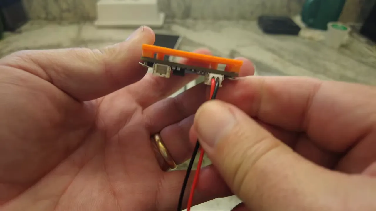
1. Prep the board and check polarity
Mount the board to a printed backing plate and confirm connector polarities before soldering. The small 2 mm plugs on these boards can be reversed at the supplier, so double-check positive-to-positive and negative-to-negative. Fixing this now avoids burning the charge circuitry later.
2. Select the solar input jumper
The SolarXaio Plus Advanced uses a jumper to select MPPT charge controller settings: 5 V, 6 V, or 12 V. Measure the panel open-circuit voltage in bright sun with a multimeter before you commit. Small 3 W panels will show around 6 to 7 V in good sun, so set the jumper accordingly to avoid overvoltage.
3. Drill an antenna hole and mount the Type N connector
Drill a 5/8-inch hole at the case top for the Type N feedthrough so the case opens front-to-back. Use the rubber seal on the connector to preserve waterproofing. Tighten the nut so the connector seals against the case, then attach the Type N to SMA adapter and antenna.
4. Mount the radio and route USB for firmware
Position the SolarXaio board so the USB port points toward an access opening. That makes flashing or debugging easier without disassembling the node. Use 3M double-sided tape on the printed mount to keep the board secure. Install the antenna connector and ensure the antenna is attached before powering up.
5. Solder and mount the battery holder
Solder the battery holder leads, add heat shrink for neatness, and secure the holder with double-sided tape or screws depending on your final layout. Hold off on inserting the battery until you have the antenna connected—never run the radio transmitter without an antenna attached.
6. Wire the solar panel and seal the cable entry
Drill a small hole for the solar cable and route it carefully. Solder the solar-positive and solar-negative to the board's solar connector. Shrink-wrap the joints and use cable ties to keep things tidy. Apply silicone around the solar panel flap on the case exterior and around the entry point to ensure a weatherproof seal.
7. Power-up, Bluetooth provisioning, and firmware
With the antenna connected and wiring double-checked, insert the 18650 cell. The nRF52840 provides Bluetooth for easy provisioning. Scan and pair with your Meshtastic app (the default pairing PIN is commonly 123456). The board often arrives with Meshtastic firmware preinstalled, but keep a USB cable handy for reflashing if needed.
8. Configure LoRa settings
Configure regional settings for LoRa (for example, United States settings for 915 MHz). Select the channel plan and power level appropriate for your region and application. Save settings in the provisioning app and monitor the device as it reboots and starts discovering nearby nodes.
9. Final seal and field testing
Once the node boots and communicates on the mesh, finish sealing the case with silicone around the solar panel and connector. Tighten the Type N nut and set the solar panel angle using the provided hinge screw for optimal sun exposure. Monitor battery voltage and message routing over the first few days to confirm the solar panel and charge controller maintain the battery.
Troubleshooting tips
- No power: Recheck connector polarity and battery orientation before applying power.
- Low solar input: Measure the panel open-circuit voltage in full sun. If it reads much lower than expected, reposition the panel or verify cabling.
- No LoRa traffic: Ensure the antenna is connected and the region/channel settings match your network.
- Boot loops: Check the charge controller jumper. An incorrect voltage selection can confuse the power rail under load.
What to expect in real deployments
A compact Meshtastic Solar node like this will typically handle small telemetry and mesh routing tasks well. Battery life depends on radio duty cycle, transmit power, firmware sleep settings, and real sunlight. Expect to iterate on jumper settings and panel tilt to reach steady-state operation. I recommend logging battery voltage and packet routes for the first few weeks to validate the system.
FAQ
How much sun does a 3 W panel need to sustain an 18650 in a typical Meshtastic Solar node?
A 3 W panel can maintain a single 18650 if the node transmits infrequently and sleep settings are aggressive. In partial sun or high-transmit scenarios you may need a larger panel or lower power settings. Measure charge current during daylight and compare with average daily consumption to be sure.
Can I run the radio without an external antenna during testing?
No. Always attach an antenna before transmitting. Running the transmitter without an antenna risks damaging the RF chain and reduces effective range.
Which jumper setting should I use for the solar input?
Choose the jumper according to measured open-circuit panel voltage. If the panel reads around 6 to 7 V in full sun, set the controller to the 6 V option. For larger panels that read near 12 V, select 12 V. The goal is to keep the charge circuit within its designed input range.
Is the SolarXaio Plus Advanced ready for Meshtastic out of the box?
Often yes. Many boards are shipped with Meshtastic firmware preinstalled, Bluetooth-enabled provisioning, and basic configuration. Keep a USB cable handy for reflashing and performing firmware updates when necessary.
How do I waterproof the solar cable and panel mount?
Use a rubber-sealed connector for the panel mount and apply silicone around the panel edges and cable entry points. Tighten feedthrough nuts for the sealed connector and let silicone cure fully before deployment.
Final notes
Meshtastic Solar nodes built on a SolarXaio Plus Advanced board provide a compact, powerful platform for mesh networks in remote and off-grid locations. With proper jumper selection, correct wiring, an antenna attached before power-up, and careful sealing of the case, a reliable node is well within reach for hobbyists and professionals.
If you build one, log performance data for the first few weeks—battery voltage, daily charge, and packet routes—so you can fine-tune solar angle, power settings, and transmit schedules.
- Wehooper4 GitHub Page - https://github.com/wehooper4/Meshtastic-Hardware/tree/main/XaioSeries/SolarXaio
- Waterproof Case - https://amzn.to/4koPUqq
- 18650 Battery - https://amzn.to/4koPUqq
- Battery Holder - https://amzn.to/4jZW9Pz
- Type N Connector - https://amzn.to/4r1aKP9
- 915Mhz Alfa Antenna - https://amzn.to/3TsSOxt